Remove the existing driver by removing the 4 screws that secure the driver to the cardboard ring. These screws are very long and we recommend use of a power screwdriver and #3 phillips bit if available.
With a wide flat instrument pry the driver away from the black spacer ring at intervals along the outer edge of driver. A dull table knife or wood chisel is a suitable tool. You will have to force the edge of the chisel between the woofers metal basket (outer rim) and the spacer ring. You might need to use a hammer or mallet to drive the chisel between the spacer and the metal rim of the woofer. This process will have to be repeated all around the woofer until it will pull away from the spacer ring.
Remove the driver and unsolder connections on the terminals taking notice of wire positioning. In this case for the new driver, the black wire goes to the positive terminal and the white wire goes to the negative terminal. If your speaker has been modified with optional wire, prior to unsoldering the original woofer be sure and note each wires color and which terminal it goes to. Duplicate these connections on the new driver.
Caulk the front face of the spacer ring with standard white or clear household caulk to ensure a good seal against new driver. Install new driver using the original hardware.
Do not use the plastic basket cover that came with the update kit. This is only used to protect the surround during shipping.
Cross-over Modification
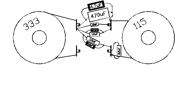
The crossover is located directly underneath the woofer. Add each capacitor (4.7uF & 1.0uF,and .47uF highlighted) in parallel as shown below. The 4.7uF capacitor included with the upgrade kit should be placed in parallel with the large 470uF electrolytic capacitor. The electrolytic capacitor will be either blue or gray and marked accordingly.
The 1.0uF capacitor should be placed across the 1.5uF capacitor. The 1.5uF capacitor will be the largest of the yellow capacitors.
The .47uF capacitor should be placed across the 1.0uF capacitor which is also yellow. The 1.0uF capacitor will be located between the original .47uF and 1.5uF capacitors.
When soldering the update capacitors in place, orientation is not important because all of the capacitors in the crossover network are non-polarized. It may be easier to position the speaker on its back directly on the floor or leaning up against a chair for installation of the crossover components.

Immediately after final assembly you should be able to play the speaker without problems before the caulk/silicone sealent is dry. We would advise only playing the speaker at moderate levels until the adhesive is cured, about 12 hours. You can check for air leaks by playing a low frequency test tone (20 or 30Hz) at a low level while listening closely (12") to the woofer box. Any leaks can be stopped by applying a small amount of sealent to the leak. Then allow it to dry. Break in can be accelerated by playing low frequency test tones from a test CD in a repeat mode. Please contact us if you have any questions.

